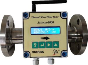
Innovative design from a leading Thermal Mass Flow Meter manufacturer and supplier
Thermal Mass Flow Meters are manufactured mainly in the Western world. These flow meters are mainly used for the flow measurement of a variety of gases and are often called Gas Flow Meters.
Manas Microsystems is one of India’s largest Gas Flow Meter manufacturers and exporters. We are perhaps the only Gas Flow Meter supplier with the capability to Manufacture, Assemble, Test, and calibrate mass flow meters for gas applications.
Designed for accuracy and reliability, our gas flow meters are suitable for various industrial applications. Some of the potential export areas for these Gas Flow Meters include Southeast Asia (SEA), the Middle East, and Africa (MEA) regions.
How does a Thermal Mass Flow Meter work?
Whenever a fluid of a certain temperature is passed over any substance hotter than the fluid, the heat of the hot substance is taken away because of forced convection by the fluid, and the temperature of that substance drops. This fall in temperature is related to the mass flow of the fluid passing over the substance. If one can measure the amount of heat taken away by the flowing fluid one can calculate the mass flow rate.
Where are Thermal Mass Flow Meters used?
Some of the applications of Thermal Mass Flow Meters include Compressed Air in various industries, Oxygen Generators, and other compressed gases, flow measurement of gases like CNG, PNG, LNG, LPG, Biogas, Nitrogen, etc.
Being a direct mass flow meter, it does not require any pressure and temperature compensation.
Thermal Mass Flow Meter- Theory Of Operation
A Thermal Mass Flow Meter contains two Platinum RTD temperature sensors for this purpose. One sensor measures the fluid temperature as a reference. The second sensor is heated and has a constant temperature differential relative to the first sensor. When the flow of air/gas starts heat is taken away from the warmer sensor. The amount of heat taken away is having a direct relation with the mass velocity of the fluid. That is how it is a direct mass flow meter.
Being a direct mass flow meter, it does not require any pressure and temperature compensation.
Features
- Direct measurement of mass flow.
- No pressure or temperature compensation required
- 20:1 turndown.
- Wireless data transfer is possible. Remote readings are available on wireless.
- Pulse, milliamps, and RS485 output for networking
Applications
- Compressed air/ Gas Consumption measurement
- Gas measurement at very low-pressure flowing conditions
- Fuel Gas like CNG consumption measurement and control
- Automobile gas engine testing
- Industrial oxygen flow measurement and control
- Furnace and burner control
- Biogas measurement in biogas digester systems

Product Details

Product Details

Product Details

Product Details
Product Details
| Model No | Scirocco 1000-1 & Scirocco 1000-2 |
| Scirocco 1000-1 | Sensor and transmitter can be mounted directly on service pipe just by drilling holes with clamps provided. (No spool pieces) |
| Scirocco1000-2 | Complete with a spool with an end connection of flange /BSP(M) Threading. |
| Service Fluid | Dry & Clean compressed Air / Gas. (Mixture of gases not applicable) |
| Line Size | DN 15 to DN 200 |
| End Connection | Flange/BSP(M) Threading/ Direct clamp mounting. |
| Accuracy | ±3 % of Actual Flow Rate between 100% to 5% of Calibrated range |
| Display | Blind/LCD 16/2. |
| Output | 4-20 mA/RS 485, Pulse, Wireless Data Transfer. |
| Ingress Protection | IP- 65 |
| Operating Fluid Temp | 0 – 100℃ |
| Operating Fluid Pressure | Up to 10 bar |
| Power Supply | 24Vdc/150mA (Without Wireless communication) 24Vdc/300mA (With Wireless Communication). |
Comparison between Vortex Flow Meter and Thermal Mass Flow Meter
| Sr. No. | Parameter | Vortex Flow Meter | Thermal Mass Flow Meter |
| 1 | Method of measurement | Measures volumetric flow that needs to be converted to mass flow, using calculations | Directly measures mass flow. Hence more reliable. |
| 2 | Pressure and Temperature Compensation | Required, as it is basically a volumetric flow meter hence signal generated is proportional to Velocity. | Not Required as the signal generated is proportional to the Mass velocity of Fluid. |
| 3 | Existing pipeline modifications for Installation | Design is based on velocity and not online size. As a result, the customer’s line size and flow meter size may differ | No Modification is essential in most the cases |
| 4 | Installation | Easy, but pipeline size matters | Very Easy |
| 5 | Recalibration | This has to be done on Flow Rig | Has to be done on Flow Rig. Relatively less expensive, as Manas offers this service at an affordable cost. |
| 6 | Suitability for low velocity | Not Suitable as vortices are not generated below 6 m/sec velocity. | Works even at velocity as low as 1 m/sec. |
| 7 | Turndown Ratio | (10: 1) | Much better (50: 1) |
| 8 | Compensation | Compensation depends on temperature. Chances of error are because of the high thermal resistance of the temperature sensor. | Compensation not required at all. Hence more reliable. |
| 9 | Error elements | There are three sensor elements – Temperature, Pressure and Flow sensor. Thus, there are three sources of error. | There is only one sensor element – Flow sensor. Hence it is more reliable. |
